

A tube component can be straightforward to model but difficult to manufacture repeatedly. Bend radii, straight lengths, material condition, wall thickness, cut features, bend rotation, tooling access and inspection requirements all affect feasibility.
There is no universal minimum distance between bends or one bend-radius rule that applies to every tube. Seaborn Manufacturing reviews the complete drawing against the available tooling and proposed manufacturing sequence before quoting production work.
Begin With the Available Bending Tooling
Rotary-draw tube bending uses fixed tooling matched to the tube size and centerline bend radius. A drawing that specifies a radius incompatible with available tooling may require new tooling or a design review. Too tight a radius will just tear the material.
Seaborn operates three CNC double stack rotary draw tube benders. Existing tooling covers numerous round and square tube sizes and approximately ¾-inch through 2-inch nominal pipe. Larger tube may be possible depending on its profile, material, wall thickness, bend radius and the complete part geometry.
Double stack tooling permits two compatible tool sets (each with a different radius) to be used within a bending program. It does not mean that any two tube sizes or bend radii can be combined automatically. Tooling compatibility and the bend sequence must be confirmed from the drawing.
Current tooling information is available on Seaborn’s CNC tube-bending service page.
Material Grade, Condition and Wall Thickness Matter
Tube size alone does not determine whether a bend is practical. The review must also consider:
Material grade and condition
Outside diameter or section size
Wall thickness
Weld-seam condition and orientation
Centerline bend radius
Bend angle
Permitted flattening, wrinkling and wall thinning
Surface condition requirements
Carbon steel is Seaborn’s most common tube bending material.
Aluminum feasibility depends heavily on the alloy and temper. The common 6061-T6 combination is highly susceptible to cracking and not suitable for bending. Seaborn has successfully bent 6061-T1 and commonly uses 6063-T5 where it is available and appropriate. The specified alloy and condition must be reviewed before quoting.
Thin wall tube, tighter radii and larger bend angles may require a mandrel, wiper or other tooling to control the tube profile. These requirements are part specific.
Straight Length Is Required for Clamping and Tooling
The bender must grip and support the tube while the bend is formed. Consequently, the straight length before, after and between bends must be compatible with the clamp.
At Seaborn, the minimum straight length between two bends is 3.3 inches. The spacing between bends increases as the tube and clamps become larger.
Round and Square Tube Behave Differently
Round tube commonly experiences some combination of flattening, wall thinning on the outside of the bend and compression or wrinkling on the inside.
Square tube presents different challenges. Its walls and corners can move during bending, particularly with tighter radii or thinner material. Some controlled deformation may be unavoidable even when the bend is structurally sound.
Holes, Slots and End Features Near Bends
Holes, slots and other cut features placed in or close to a bend can move or distort as the tube forms. Their final position depends on the material, bend geometry, feature shape and manufacturing sequence.
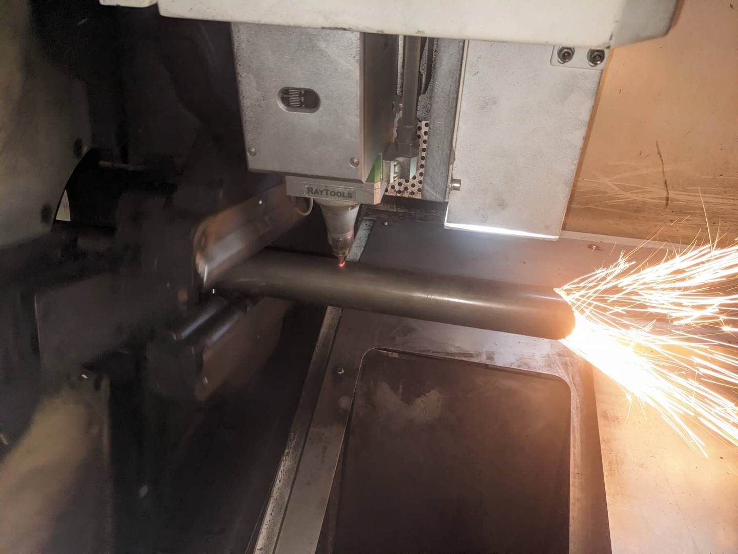
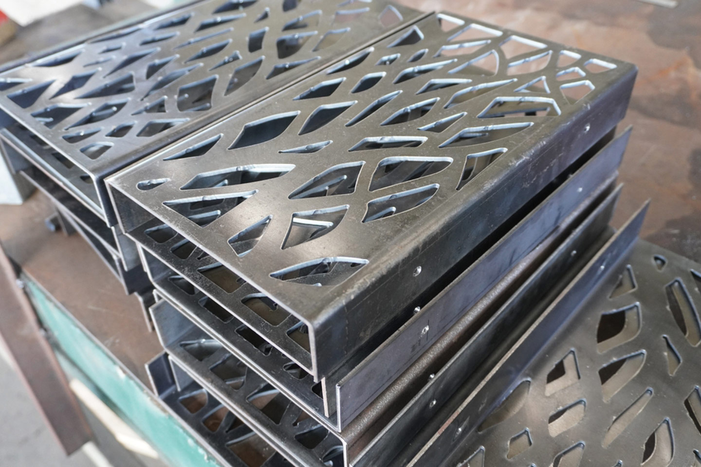
Seaborn’s tube-laser cutting can produce holes, slots and end profiles before bending. This can reduce secondary operations and provide locating features for welding and assembly. It does not make every pre-cut feature suitable for placement inside a bend.
Where a feature has a critical relationship to a finished bend, the drawing review should determine:
Whether it can be cut before bending
Whether expected movement is acceptable
Whether it should be produced after bending
Which datum controls its final location
How it will be inspected
The correct sequence depends on the finished component, not simply on which operation is performed first.
Multi-Plane Parts Require a Complete Collision Review
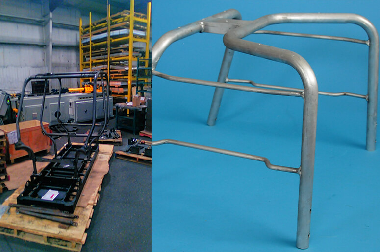
Multi-plane tube components require controlled rotation between bends. The program must account for the rotational relationship, bend sequence, tooling clearance and the position of the formed tube throughout the cycle.
A part may be difficult or impossible to complete if a previous bend collides with the machine, tooling, floor or another portion of the tube. Reversing the starting end or adjusting a straight section may resolve the problem, but the complete geometry must be reviewed.
A flat drawing should clearly define bend rotation. A 3D CAD model can be useful for multi-plane components, but it does not replace the controlled drawing.
Tolerances and Inspection Must Match the Part
Machine positioning accuracy is not automatically the tolerance of the finished tube component. Material variation, springback, accumulated bends, tube rotation and the selected datums all affect the final result.
A production drawing should clearly identify:
Tube size and wall thickness
Material grade and condition
Centerline bend radii
Bend angles
Straight lengths or bend locations
Rotation between bend planes
Critical datums and interface dimensions
Inspection and documentation requirements
Seaborn may inspect bent components using conventional measuring equipment or a dedicated go/no-go fixture. Dedicated fixtures are often effective for repeat production parts because they verify the functional relationship between several features efficiently.
Additional guidance is available in Manufacturing Tolerances for Fabricated Parts.
Information Required for a Production Review
Provide the following when requesting a tube-bending quotation:
Controlled drawing with revision level
Available 3D CAD data (does not replace drawings with tolerances)
Material grade and condition
Tube diameter or section size
Wall thickness
Centerline bend radii and bend angles
Bend locations and multi-plane rotations
Cut features and finished-length requirements
Critical tolerances and inspection requirements
Quantity per release and anticipated annual volume
Required welding, finishing, hardware or assembly
Seaborn then evaluates tooling compatibility, bend sequence, tube-laser operations, fixtures and inspection requirements for repeat production.
The Drawing and Quotation Govern
Published design guidance cannot replace a part-specific manufacturing review. A practical tube design must work with the selected material, tooling, manufacturing sequence and inspection method.
Seaborn Manufacturing produces built-to-print bent tube components and fabricated tube assemblies for recurring OEM and industrial requirements.
Send Seaborn your drawings and production requirements for review.