

A coordinate measuring machine can measure locations and geometric relationships very accurately. That does not mean it is the correct inspection method for every manufactured component.
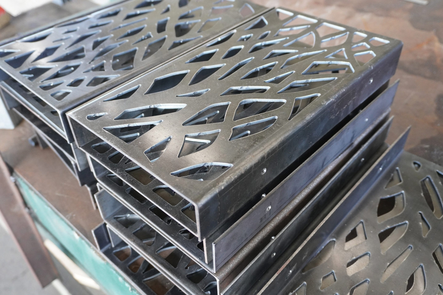
A CMM is generally most effective on rigid, stable parts with well-defined features. Thin material and many laser cut, formed or welded components present different challenges. Part flex, how the component is supported or restrained, surface variation and the selection of measurement points can all affect the result.
For these parts, a CMM can indicate that a component is acceptable when it is not or reject a component that would function correctly. The inspection method must therefore be selected for the actual part and its intended function.
What a CMM Actually Measures
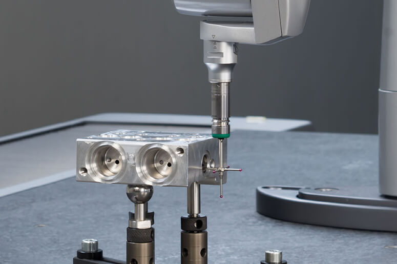
A tactile CMM operates in a point probing mode records coordinates at selected locations where the ruby ball contacts the part. The software uses those points to construct geometric features such as lines, planes, circles and cylinders.
The machine is not directly observing the entire physical feature. It is calculating a feature from the points that were measured.
When a feature is created from only a few points, the location of each point matters greatly. A small local deviation, surface roughness or burr at one of three measured points can substantially change the calculated feature. Even one point out of a dozen can have significant impact. Measuring more points may provide a better representation, but it does not correct a part that has moved, flexed or restrained into a different shape.
A report containing measurements to several decimal places can appear highly precise while still failing to represent the functional condition of the part.
Where CMM Inspection Works Well
CMM inspection is well suited to rigid components that remain stable while being measured. It can be effective for:
Machined holes, bores, bosses and surfaces
Defined relationships between rigid features
Components with repeatable and accessible datums
Parts that can be supported without changing their geometry
Repeated inspection using a controlled measurement program
Applications requiring documented dimensional results
Under these conditions, selected measurement points can provide a useful representation of the actual feature.
Thin and Flexible Parts Can Produce Misleading Results
Thin sheet metal and other flexible components do not always maintain one fixed shape. The part may sag under its own weight, sit differently depending on its supports or move when it is held down.
Probe contact is rarely the main problem. The larger concern is the condition of the part while it is being measured.
Holding a thin component down can flatten, twist or otherwise move it into a different condition. Leaving it unrestrained may allow it to sag or move. The CMM then measures whichever condition has been created by the support or restraint method.
Unless that condition represents how the component functions in its final assembly, the result may be misleading. The CMM can make the part appear either good or bad and be wrong in either direction.
Thin Edges Are Difficult to Probe Reliably
The ruby ball must contact the intended surface of the feature. On a thin edge, reliably contacting near the middle of the ruby can be difficult.
The probe may instead be influenced by:
The upper or lower edge of the material
A burr or small radius
Local surface roughness
Laser cut taper or striation
A minor deformation at the selected point
The CMM may accurately report the coordinate of the contact it made, but that contact may not represent the intended edge or feature.
When only a few points are used to construct a line, plane or circle, a small difference at one contact location can produce a much larger difference in the calculated result.
Fabricated Parts Are Not Machined Parts
Laser cut, formed and welded parts commonly contain normal variation that differs from the surfaces and features found on rigid machined components.
This may include:
Surface roughness or taper along laser cut edges
Burrs or local edge variation
Bow, twist or springback in formed components
Weld distortion
Irregular nonmachined surfaces
Tube flattening or movement through a bend
Components that change shape when supported or restrained
A small number of touch points may not properly represent these conditions. Increasing the number of points can provide more information, but it does not automatically make CMM inspection the best method.
Restraint Must Represent the Intended Condition
Some fabricated parts are designed to be pulled into position by fasteners or held against mating components during assembly. Others must meet their requirements in a free state.
This distinction must be understood before inspection.
If a component is intended to function while restrained, an inspection fixture may need to reproduce that condition. If it is intended to meet its tolerances without restraint, holding it flat during inspection could conceal a problem.
The method of supporting and holding the part can determine the result. A measurement report has limited value unless the inspection condition is clearly defined and relevant to the finished assembly.
Other Inspection Methods May Be More Appropriate
A CMM is one inspection tool. It is not automatically more suitable than conventional measuring equipment or a dedicated fixture.
Depending on the component, inspection may be better performed using:
Calipers and micrometers
Height gauges and surface plates
Pin gauges
Angle gauges
Templates
Dedicated go/no-go fixtures
Functional checking fixtures
Trial assembly against mating components
For repeat production parts, a functional fixture can efficiently confirm whether several important features relate correctly to one another. This may provide more useful information than individually calculated features that do not represent how the component fits or functions.
The Drawing and Inspection Plan Must Work Together
The drawing should identify the dimensions, datums and tolerances that control the function of the finished component. The inspection plan should then establish a suitable method for verifying those requirements.
The review may need to determine:
Whether the part is inspected in a free or restrained condition
How the part will be supported
Which datums control the measurement
Whether the measured surfaces are suitable for probing
Whether local surface variation could influence the result
Whether a direct measurement or functional fixture is more appropriate
What inspection records are required
Specifying CMM inspection does not correct a tolerance or datum structure that is unsuitable for a thin or fabricated component.
Additional guidance is available in Manufacturing Tolerances for Fabricated Parts.
Select the Inspection Method for the Part
CMM inspection can provide useful and repeatable results when the component, features, support method and measurement program are suitable. It can also produce incorrect acceptance or rejection decisions when applied to thin, flexible or irregular fabricated parts without accounting for how those parts behave.
Seaborn Manufacturing uses CMM inspection, conventional measuring equipment and dedicated fixtures according to the component geometry, material, tolerances, production quantity and functional requirements.
Send Seaborn your drawings and inspection requirements for review.