

Manufacturing tolerances cannot responsibly be reduced to one standard table. A tolerance achievable on an individual laser-cut feature may not remain achievable after the part is formed, welded or incorporated into an assembly.
Material grade and condition, thickness, part size, feature geometry, datum selection, manufacturing sequence and inspection method can all affect the result. For this reason, Seaborn Manufacturing reviews tolerances against the controlled drawing and proposed manufacturing process before quoting production work.
The values discussed below describe practical process considerations. They are not blanket guarantees. The approved drawing and Seaborn’s quotation define the requirements for any order.
A Process Capability Is Not a Part Guarantee
A machine’s positioning accuracy does not automatically establish the tolerance of a finished component.
For example:
Sheet thickness is a material characteristic, not a laser-cutting tolerance.
Tube outside dimensions, wall thickness and corner radii can vary before manufacturing begins.
Forming introduces material movement and springback.
Welding introduces heat and can cause dimensional movement.
A tolerance without a defined datum or inspection method may be interpreted differently by different suppliers.
Critical dimensions should therefore be identified separately from non-critical dimensions. The manufacturing and inspection plan can then concentrate control where it affects fit, function and assembly.
Sheet and Plate Laser-Cutting Tolerances
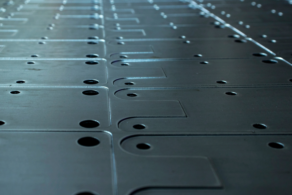
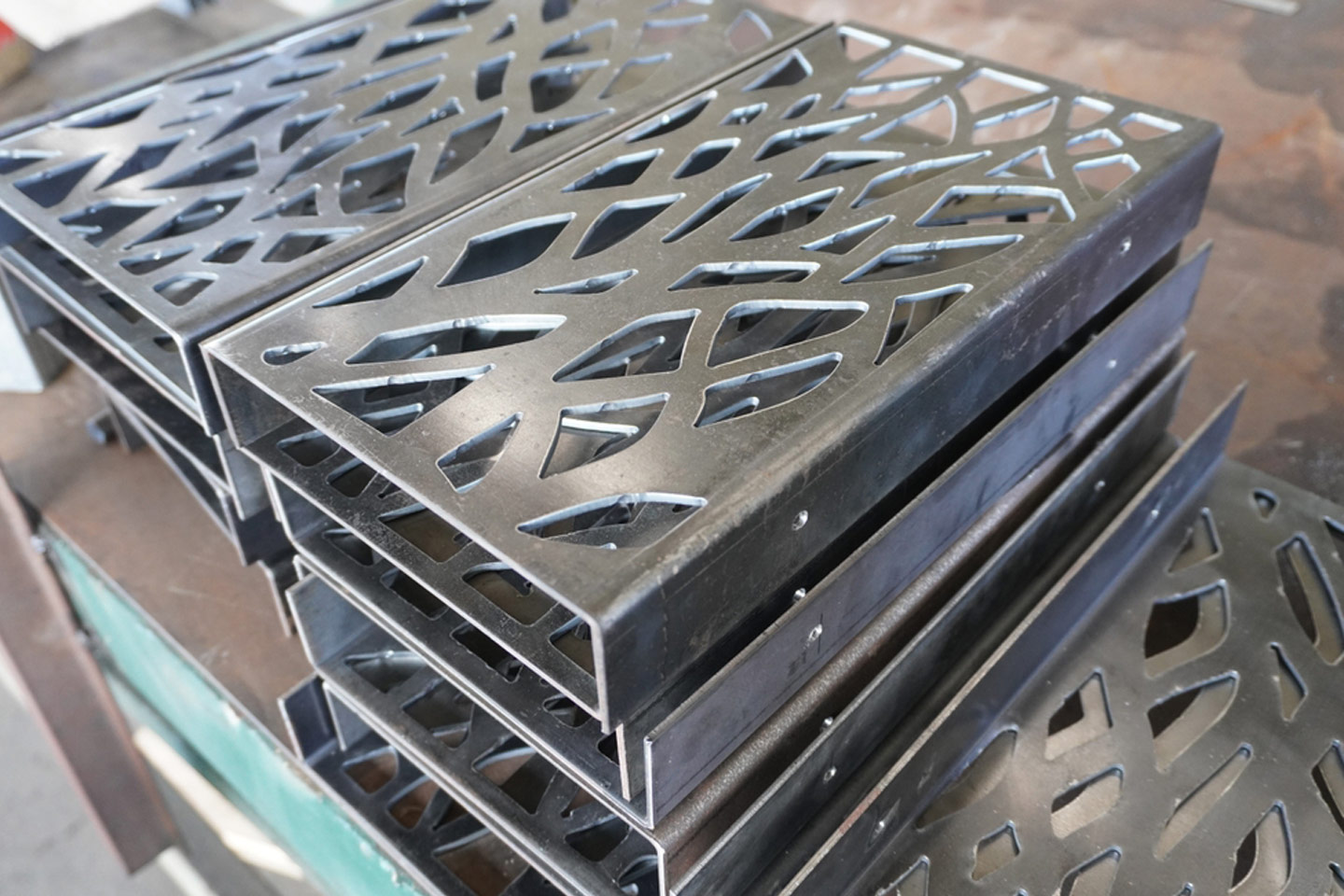
For suitable sheet-metal parts, individual laser-cut features can often be held to approximately ±0.005 in. (±0.127 mm). This should not be applied automatically to every dimension on every laser-cut part.
Achievable results depend on:
Material grade and thickness
Part and feature size
Hole diameter relative to material thickness
Heat input and part geometry
Edge-condition requirements
The location and relationship of critical features
Whether the part will subsequently be formed, welded or machined
Heavy plate, small features, closely spaced cuts and parts vulnerable to thermal movement require individual review.
Seaborn provides sheet and plate laser cutting for carbon steel, stainless steel and aluminum production components. Material, geometry, tolerances and required edge condition are confirmed from the drawing before quoting.
Tube-Laser Tolerances and Incoming-Material Variation
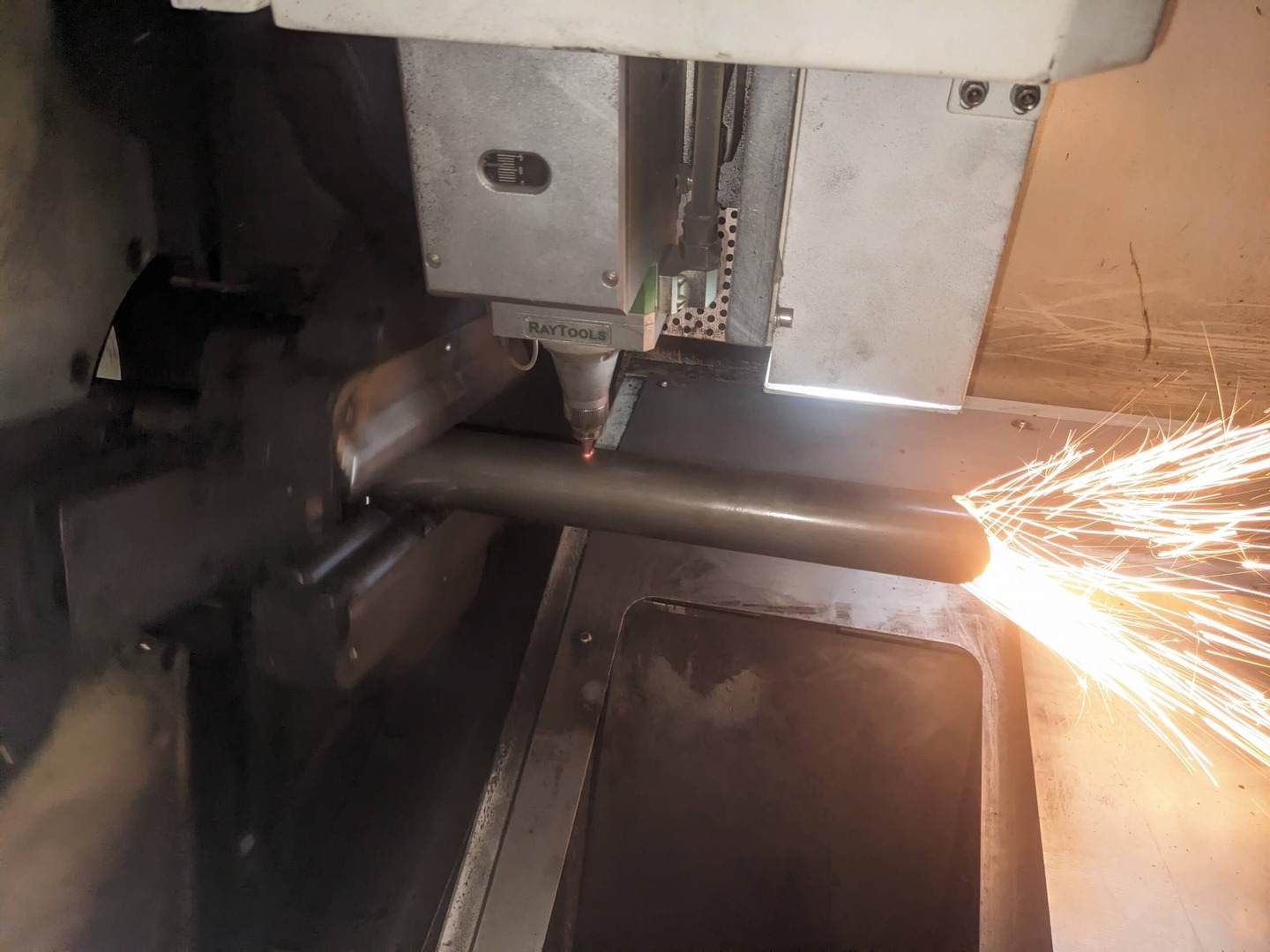
On suitable tube-laser components, individual cut features can typically be held to approximately ±0.005 in. (±0.127 mm). Feature-to-feature dimensions across longer parts may require approximately ±0.010 in. (±0.254 mm), depending on the part length and condition of the tube.
Tube-laser features are programmed from the tube centreline. Dimensions taken from an outside tube surface can be affected by normal variation in:
Outside dimensions
Wall thickness
Straightness
Ovality
Corner radii
Twist over the stock length
These material characteristics become particularly important when a drawing locates a hole or slot from an outside edge rather than from the tube centreline or another functional datum.
Seaborn’s tube-laser cutting page provides additional information about profiles, material limits, feature positioning and production capabilities.
Press-Brake Forming and CNC Tube Bending
Press-brake and tube-bending tolerances depend on more than the programmed machine position. Material strength, thickness, grain direction, bend radius, tooling, springback and the relationship between bends all affect the finished part.
For press-brake parts, important considerations include:
Bend-angle tolerance
Flange length
Hole or feature location after forming
Accumulated dimensions across multiple bends
Material thickness and strength variation
The datum used to inspect the formed component
For CNC tube-bending parts, the review may also include:
Tube profile and wall thickness
Centreline bend radius
Straight length between bends
Bend rotation and multi-plane orientation
Ovality and wall thinning
Mandrel requirements
The effect of cut features added before bending
Fixture or gauge requirements for repeat inspection
Seaborn uses three CNC double-stack rotary-draw tube benders for repeat-production components. The appropriate tooling, bend sequence and inspection method are determined from the drawing. Additional information is available on our CNC tube-bending page.
Tolerances on Welded Assemblies
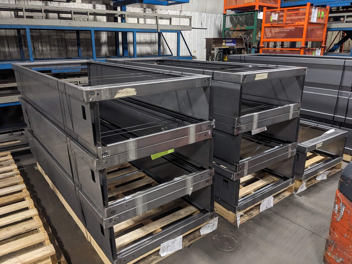
A welded assembly should not be assigned one universal tolerance. Finished accuracy depends on the component tolerances entering the fixture, joint design, weld size, heat input, welding sequence and the stiffness of the assembly.
Fixtures and controlled welding procedures support repeatability, but they do not eliminate thermal movement. A practical drawing should distinguish dimensions that control function or assembly from dimensions that do not require the same level of control.
Important requirements may include:
Overall length, width and height
Hole and mounting-feature locations
Flatness of mounting surfaces
Angular relationships
Interface dimensions
Weld symbols and acceptance requirements
Inspection points and datum references
Seaborn uses manual and robotic welding, modular 3D welding tables and controlled fixtures for repeat-production components and fabricated assemblies. Seaborn is CWB certified to CSA W47.1 and W47.2 Division 3.
Machined Features and Surface-Finish Requirements
Machining may be incorporated where a fabricated component requires controlled holes, mounting interfaces or other critical features. Machining requirements must be evaluated in relation to the manufacturing sequence, particularly when welding or forming occurs after a feature is machined.
Surface finish should also be specified separately from dimensional tolerance. Terms such as “smooth,” “fine” or “cosmetic” are open to interpretation.
Where surface roughness is functionally important, the drawing should identify:
The required roughness parameter, such as Ra
The units of measurement
The surface or area to which it applies
Any direction-of-lay requirement
Whether the requirement applies before or after coating, welding or another operation
Laser-cut edges, formed surfaces, machined faces, ground areas and welded joints should not be assumed to have the same finish.
Inspection Must Match the Requirement
The inspection method should be appropriate for the tolerance and the production volume. Depending on the component, Seaborn may use conventional measuring equipment, a coordinate measuring machine or a dedicated go/no-go fixture.
Dedicated fixtures can be particularly effective for repeat-production tube components and welded assemblies because they verify the functional relationship between multiple features efficiently. A coordinate measuring machine may be appropriate when dimensional reporting or more detailed geometric verification is required.
The required inspection records, sampling frequency and acceptance criteria should be established before production rather than inferred after parts have been manufactured.
How Seaborn Reviews Production Tolerances
For a meaningful review, Seaborn requires a controlled drawing that identifies the current revision, material, tolerances and acceptance requirements. Available CAD data helps define geometry but does not replace the controlled drawing.
The review should also establish:
Material grade, condition and thickness or tube section
Critical dimensions and functional datums
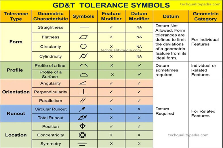
Applicable geometric tolerances
Required manufacturing operations
Inspection or documentation requirements
Quantity per release and anticipated annual volume
Any mating components or assembly requirements
Seaborn then evaluates the process route, tooling, fixtures and inspection requirements needed to produce the part repeatedly.
The Drawing and Quotation Govern
Published process figures are useful for early discussion, but they cannot replace a part-specific manufacturing review. Applying unnecessarily tight tolerances throughout a drawing can increase tooling, setup, inspection and production costs without improving the component’s function.
Seaborn Manufacturing produces built-to-print components, weldments and fabricated assemblies for recurring OEM and industrial requirements. Our metal-fabrication services combine laser cutting, tube processing, forming, machining, welding, inspection and assembly where the production requirement is a suitable fit.
To have a production requirement reviewed, send Seaborn your drawings and RFQ.


