

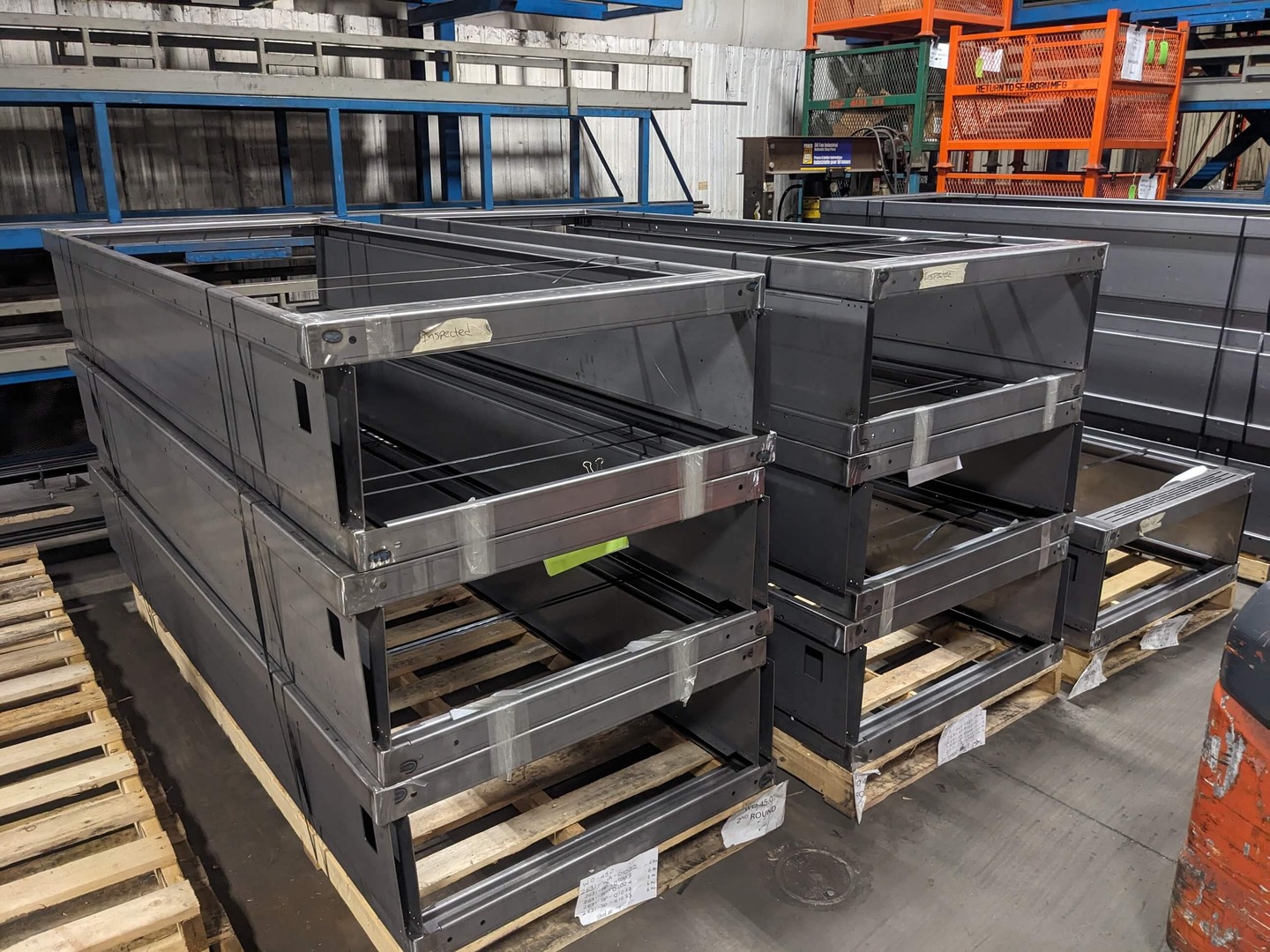
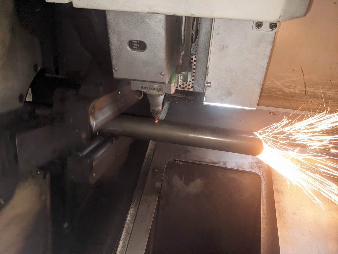
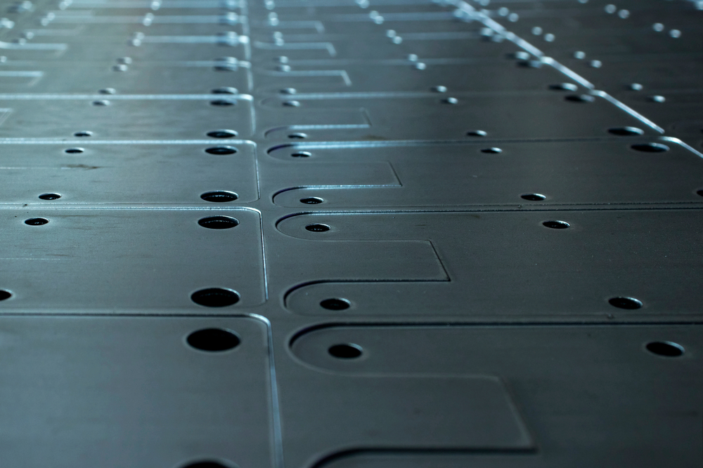
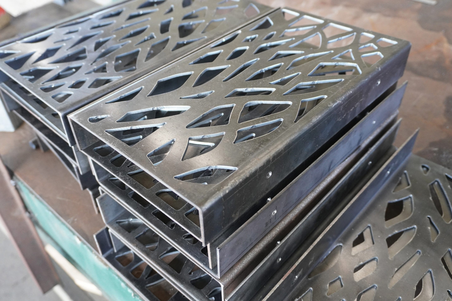
A sheet metal component may be easy to model but difficult or even impossible to form repeatedly. Material grade, thickness, bend radius, flange length, tooling, feature location, bend sequence and tolerance requirements all affect the finished part.
There is no single design rule that applies to every press brake component. Seaborn Manufacturing reviews the complete drawing against the material, available tooling and proposed manufacturing sequence before quoting production work.
Begin With the Material and Available Tooling
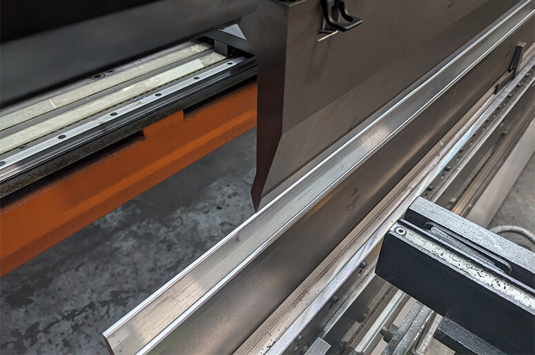
A press brake forms sheet or plate between a punch and a die. The resulting bend depends on the tooling geometry, die opening, material thickness and programmed ram position.
Seaborn uses CNC press brakes with precision ground and segmented tooling for repeat production components. Equipment includes a 12 ft, 175 ton press brake with seven-axis control. Actual forming capacity depends on the material, bend length, die opening, and completed part geometry.
A part that cannot be formed with available tooling may require different tooling, an adjusted design or another manufacturing method. Tooling requirements should therefore be reviewed before the flat blanks are released for production.
Additional capability information is available on Seaborn’s sheet metal bending service page.
Material Grade and Condition Matter
Material thickness alone does not determine how a part will bend. The review should also consider:
Material grade and condition
Actual thickness range
Tensile and yield strength
Bend angle
Bend length
Surface condition requirements
Permitted marking, cracking or distortion
Carbon steel, stainless steel and aluminum respond differently during forming. Even material supplied to the same nominal specification can produce some variation in bend angle and finished dimensions.
Aluminum alloy and temper require particular attention. 5052-H32 generally forms readily, while 6061-T6 will not form. The specified alloy and temper must be reviewed before production.
Minimum Flange and Return Lengths Depend on the Tooling
The material must remain properly supported by the die while the bend is formed. A flange or return that is too short for the selected die opening may pull into the die instead of forming correctly.
The required minimum flange length depends on:
Material thickness
Die opening
Available backgauge support
A fixed multiple of 8 times the material thickness should be treated as an early design guide. Short returns may not be possible or practical to form.
Holes, Slots and Other Features Near a Bend
Holes, slots, countersinks and other cut features can stretch or distort when located within the area affected by forming. The amount of movement depends on the feature shape, material, thickness, bend radius and distance from the bend.
The drawing review should determine:
Whether the feature can remain in its proposed location
Whether some distortion is acceptable
Whether a bend relief is required
Whether the feature should be produced after forming
Which datum controls its finished location
How the feature will be inspected
Seaborn’s laser cutting service can produce flat blanks with holes, slots, reliefs and other features before forming. This does not make every laser cut feature suitable for placement close to a bend.
Bend Reliefs, Chamfers and Irregular Edges
Fillets, chamfers and irregular edges that extend into the bend area can cause uneven material support. The part may twist, pull sideways or form differently along the bend line.
Bend reliefs can help separate adjacent flanges and control tearing or unwanted deformation. Their size and location should be reviewed in relation to the material thickness, bend radius and finished corner requirement.
Forming from an edge that is not parallel to the bend line may also require additional setup or special tooling to control the part.
Flat Patterns and Bend Allowances
The finished dimensions of a formed component depend on the bend allowance or bend deduction used to develop the flat blank. These values are affected by the material, thickness, tooling and forming method.
A flat pattern generated using default CAD settings may not match the production tooling. Where Seaborn is responsible for both laser cutting and forming, the flat blank can be verified using the intended production process.
The controlled drawing should define the required finished dimensions. CAD data supports manufacturing but does not replace the drawing or its tolerances.
Bend Sequence and Tooling Clearance
Parts with multiple bends must be reviewed as a complete forming sequence. A bend that is possible on a flat blank may become inaccessible after another flange has been formed.
Boxes, channels, Z shapes and parts with return flanges can collide with the punch, die, ram or previously formed sections. The review may require:
Changing the bend sequence
Reversing the part orientation
Using segmented or alternate tooling
Adjusting a flange or return
Dividing the component into multiple pieces
Welding the pieces after forming
The appropriate solution depends on the complete geometry and production quantity.
Tolerances and Inspection Must Match the Finished Part
Machine positioning accuracy is not automatically the tolerance of a finished formed component. Material variation, springback, bend sequence and accumulated dimensions across several bends all affect the result.
A production drawing should clearly identify:
Critical finished dimensions
Functional datums
Bend angles
Flange and return lengths
Hole and mounting feature locations
Inspection and documentation requirements
A dimension taken across several bends may require more tolerance than a dimension controlled by one bend. Requirements should be concentrated where they affect fit, function or assembly.
Additional guidance is available in Manufacturing Tolerances for Fabricated Parts.
Information Required for a Production Review
Provide the following when requesting a press brake quotation:
Controlled drawing with revision level
Available 3D CAD data (does not replace drawings with tolerances)
Material grade and condition
Material thickness
Finished dimensions and bend angles
Critical datums and tolerances
Inspection and documentation requirements
Quantity per release and anticipated annual volume
Required welding, finishing, hardware or assembly
Seaborn then evaluates the flat pattern, tooling, bend sequence, setup and inspection requirements needed for repeat production.
The Drawing and Quotation Govern
Published design guidance cannot replace a manufacturing review specific to the part. A practical press brake component must work with the selected material, tooling, forming sequence and inspection method.
Seaborn Manufacturing produces built to print formed components and fabricated assemblies for recurring OEM and industrial requirements. Our metal fabrication services combine laser cutting, forming, machining, welding, inspection and assembly where required.
Send Seaborn your drawings and production requirements for review.