At Seaborn Manufacturing, we know that precision starts before the first piece of metal hits the shop floor. One of the truly critical steps in any successful project is the quality of the CAD files submitted for manufacturing. In our years serving clients with metal fabrication Hamilton, we’ve learned that the difference between a great job and a problematic one often lies with how the drawings were prepared.
If you want to get the most value for your machining or tube laser cutting, dollars your CAD files must communicate clearly, and accurately all information required. For any manufacturer or fabricator, unclear or incomplete drawings can create delays, miscommunication, and avoidable rework. Below are some practical, work proven tips that can help ensure your next CAD submission supports a fast, cost effective and accurate build.
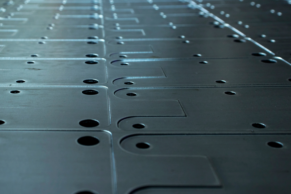
The first and most important step is to make sure all your dimensional data is correct. Hole sizes and locations should be precise, with special attention given to maintaining consistency across all views. It’s not an issue to leave adjusting final blank sizing for forming to the fabricator, but feature placement on each face should be perfect, everything should be correct.
Avoid referencing from feature to feature, these kinds of “daisy chained” measurements are more prone to error and can be officially corrected when errors stack up. Instead, use a fixed, known reference point. Modern CNC machinery gives more than sufficient tolerance on point to point locations ie mounting hole pitches etc.
For parts to be CNC milled, we recommend drawings be dimensioned from the top left corner with Z-zero set to the top surface. This is a common standard that matches the typical programming datum. This minimizes confusion, setup time and makes minor tweaks easier.
For CNC turned parts, ideally dimensions should be taken from one end, and the various diameters should be clearly labeled.
Avoid dimensioning to the center of radii unless absolutely necessary. This is not a location a machinist or fabricator can find by hand. This often requires additional inspection time and specialized tools like a CMM, which can increase your costs.
When possible use ordinary dimensioning, which is our most manufacturers preferred method. It provides a cleaner and more error resistant layout compared to chain dimensions.
When applying tolerances, it’s ideal to express them in a symmetric format such as ±0.01. For example, a dimension listed as 0.5 +0.02 should instead read 0.51 ±0.01, this provides the same precision, but is clearer for both programming and inspection.
Features with a tolerance should be drawn at mid-range whenever possible. This allows the programming automation to do its job.
A frequent oversight we see in metal fabrication Hamilton projects is lack of proper revision tracking. Every time a part’s revision changes, the corresponding assembly revision(s) should also be updated. The assembly drawings should list the revision level of each component with in the B.O.M.. This simple step is the best insurance to avoid costly errors.
The term “typical” should be used sparingly and with clarity. When calling out something as “typical,” specify exactly which features it applies to and in what context. The vague use of “typical” can lead to assumptions that vary between designers and fabricators, and the result is often not aligned with the intent.
Pro Tip: do not be afraid to leave hidden lines turned on for part drawings. While many designers prefer clean views, hidden lines often help trades, quality, and manufacturers verify critical features that are not clear in the view otherwise. This is especially helpful when confirming depths, through holes or one blind, internal features, or counterbores without needing to open CAD models. If the CAD models are 2D and stripped even that won’t help. The purpose of the design drawing is to convey all the required information.
We encourage our clients to think about what the fabricator needs. For example, while blank sizing may be left to the shop, the critical cut feature ie. holes, notches, etc. must be explicitly defined.
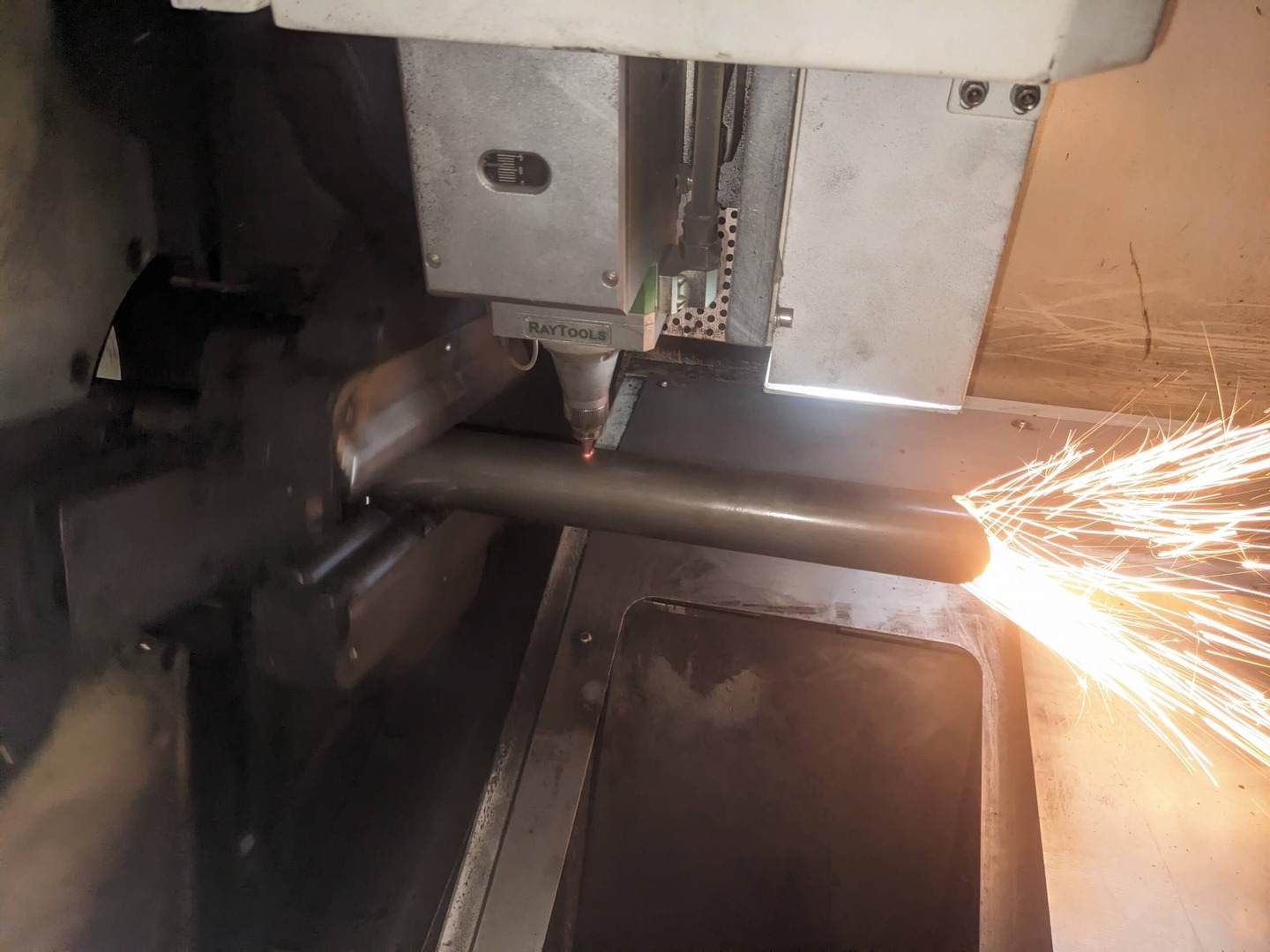
At Seaborn Manufacturing, we believe strong communication begins with strong documentation. Whether preparing for a tube laser job or a multi-axis CNC machining setup, submitting complete, well-structured CAD files can make a world of difference. Serving the metal fabrication Hamilton region and beyond, we’ve built our reputation on delivering precision with efficiency, and this starts with your design.
Your drawings are more than just instructions; they are the blueprint for your success. Get them right, and everything else follows. To learn more about what Seaborn Manufacturing can do to support your next project, contact us today. We’re proud to be a trusted name in metal fabrication Hamilton, and serve all of Ontario.